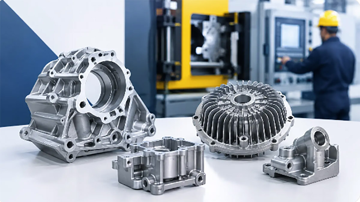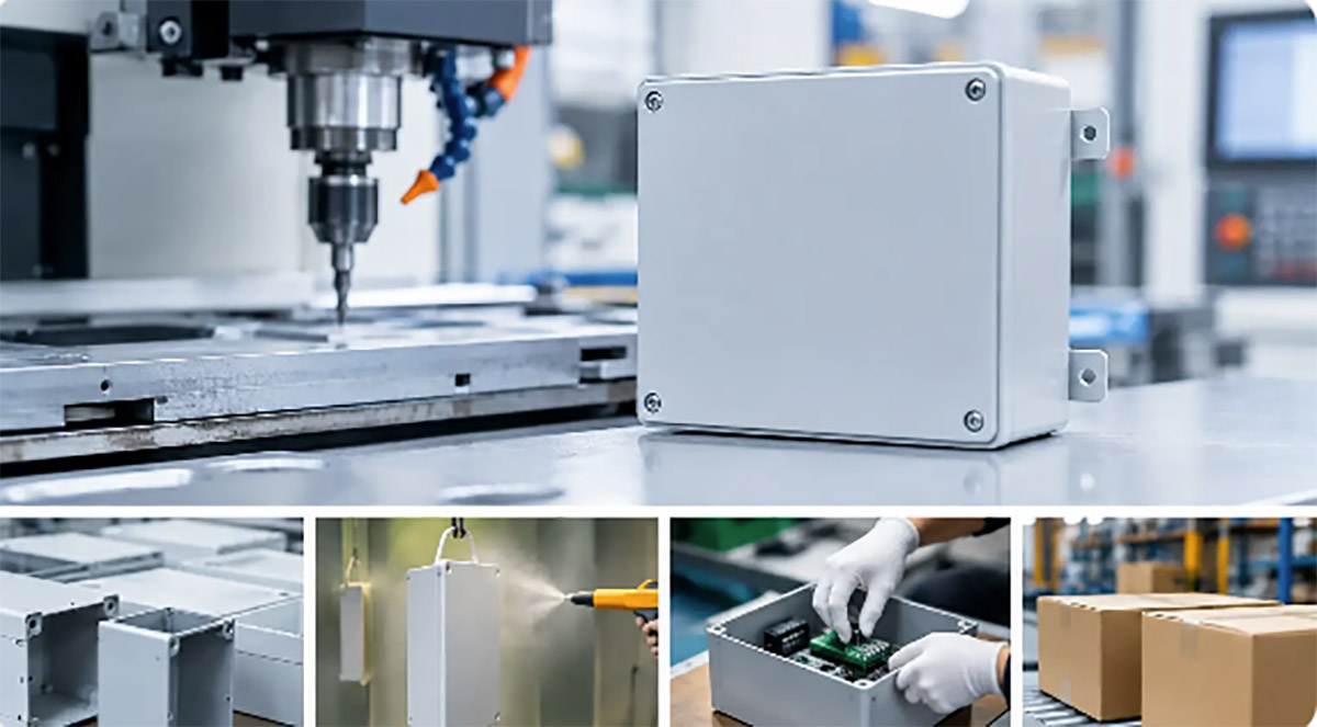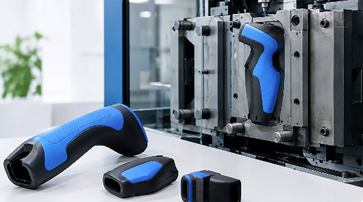
CNC machining supports fast prototypes, fixtures, and production parts with tight tolerances, stable quality, and efficient scaling.

CNC Machining for Prototypes and Production
A part can look straightforward on a screen
and still become expensive, slow, or unstable once it reaches the shop floor.
That gap is where cnc machining matters most. For product teams, engineers, and
sourcing managers, the value is not just that a machine can cut metal or
plastic accurately. It is that cnc machining provides a controlled, repeatable
way to move from prototype to production without changing the core
manufacturing logic every time volume increases.
For outsourced manufacturing, that
predictability has practical consequences. It affects quote speed, tolerance
risk, fixture design, assembly fit, cosmetic consistency, and lead time
planning. When a supplier can machine early prototypes, revise designs based on
actual process feedback, and then support pilot or repeat production, the
development path becomes much easier to manage.
What cnc machining is really used for
In technical terms, cnc machining is a
subtractive process that removes material from solid stock using programmed
toolpaths. In purchasing and product development terms, it is one of the most
flexible manufacturing methods available. It works well for one-off functional
prototypes, low-volume bridge builds, jigs and fixtures, mold components, and
end-use parts that require stable tolerances.
That flexibility is why it shows up across so
many product categories. Electronics housings, brackets, heat sinks, medical
device components, consumer product details, inspection fixtures, and assembly
aids are common examples. The process is especially useful when a team needs
real material properties before committing to tooling, or when annual volume
does not justify an injection mold or die casting tool.
The key point is that cnc machining is not automatically
the cheapest process. It is often the most efficient process at a specific
stage of the product lifecycle. That distinction matters when comparing cost.
Where cnc machining fits in product development
Early-stage programs usually need speed and
design freedom more than piece-price optimization. At that stage, machining
allows teams to validate dimensions, wall sections, assembly interfaces, and
mechanical performance using production-like materials. Changes can be
implemented through revised programs rather than waiting for new tooling.
Once a design starts stabilizing, machined
parts often support pre-production testing, customer samples, certification
builds, and pilot runs. This is where many projects benefit from a
manufacturing partner that also handles tooling and downstream production
processes. The handoff is smoother when the same team has already reviewed the
design for machinability, part function, and future scale-up.
For some products, machining remains the
long-term process. That is common for moderate volumes, highly customized
components, precision assemblies, and parts with geometry that would make
tooling unnecessarily complex. For other products, machining is a bridge to injection
molding, die casting, stamping, or silicone
tooling. The decision depends on volume, tolerance, material, finish
requirements, and how often the design may change.
CNC machining materials and process trade-offs
Material selection has a direct effect on
price, lead time, and manufacturability. Aluminum is a frequent choice because
it machines efficiently, offers good strength-to-weight performance, and
supports a wide range of finishes. Stainless steel is common when corrosion
resistance or added strength is needed, but machining time is usually higher.
Brass, copper, and tool steels are also used depending on electrical, thermal,
or wear requirements.
On the plastic side, ABS, POM, nylon,
acrylic, PEEK, and polycarbonate all appear in machined prototypes and
production parts. Each behaves differently during cutting. Some hold fine
features well, while others may warp, chip, or require more careful support. If
the machined plastic part is meant to represent a future molded part, the
selected grade should be reviewed carefully. A prototype that looks right but
does not match final mechanical behavior can create avoidable problems later.
Tolerance expectations need the same kind of
review. Tight tolerances are achievable, but they should be applied where they
serve function. Over-tolerancing raises inspection burden, extends machining
time, and can increase scrap risk without improving product performance. A good
manufacturing review usually separates critical mating or sealing dimensions
from non-critical surfaces so cost is controlled without weakening the design
intent.
Design decisions that improve cnc machining
results
The fastest way to reduce machining cost is
often to simplify the design before production begins. Deep pockets, narrow
internal radii, thin walls, and hard-to-reach features can all push cycle time
higher. Multi-sided machining and secondary setups are normal, but every added
setup introduces time and the potential for variation.
This does not mean complex parts should be
avoided. It means complexity should be intentional. If a radius exists because
a cutting tool requires it, that is practical design. If a cosmetic surface
needs a separate operation, that should be planned. If a tolerance stack
affects assembly, datums and inspection strategy should be discussed early
instead of after parts arrive.
For many OEM programs, the most useful
supplier input is DFM
support before the first chips are cut. Small
changes such as adjusting corner geometry, revising thread depth, adding
reliefs, or changing stock size can improve throughput without changing product
function. When the same supplier also supports assembly or complete product
builds, those changes can be evaluated against the full manufacturing workflow
rather than in isolation.
CNC machining for prototypes versus production
Prototype machining and production machining
are related, but they are not identical purchasing decisions. In prototype
work, speed and engineering feedback usually matter most. Teams want to learn
quickly, confirm fit, and identify design problems before spending on tools or
committing to inventory.
In production, repeatability becomes the
priority. The process needs stable fixtures, defined inspection criteria,
controlled revision status, and material traceability where required. Surface
finish consistency and packaging can also become more important once parts are
moving into an assembly line or end-customer shipment.
This is one reason supplier capability should
be evaluated beyond machine capacity alone. A shop that can produce a few
accurate samples is not necessarily set up to manage recurring orders, incoming
material control, process documentation, sub-supplier coordination, and
assembly support. For buyers managing schedules across multiple custom parts,
those operational details often determine whether a project runs smoothly.
Quality control in cnc machining
Quality in cnc machining starts before the
machine runs. Drawing clarity, tolerance hierarchy, material callouts, and
finish specifications all influence results. Ambiguous prints create avoidable
variation, especially when multiple parts must fit into a larger assembly.
During production, quality control usually combines
in-process checks, final inspection, and documentation aligned to the part's
risk level. Critical dimensions may require first article verification, gauge
control, or CMM inspection. Cosmetic parts may need approved appearance
standards. Components used in assemblies may also need trial fitting before
release.
The right inspection level depends on the
application. A fixture for internal factory use does not need the same control
plan as a visible consumer product component or a precision interface part.
Matching the inspection strategy to the actual use case is part of keeping cost
realistic while maintaining quality.
Choosing a cnc machining partner
For most buyers, supplier selection comes
down to execution. Can the partner review files quickly, identify process risks
early, and recommend a practical route from sample to production? Can they
machine parts, support revisions, and coordinate related processes such as
finishing, tooling, molding, sourcing, and assembly when the project expands?
That broader capability matters because
manufactured products rarely stay within one process forever. A machined
prototype may lead to an injection molded housing, a cast metal part, a
silicone keypad, and a final assembled unit. Working with a partner that
understands those transitions can reduce handoff delays and prevent local optimizations
that create larger production problems later.
Xiamen Creator Technology supports this kind
of workflow by combining cnc machining with prototyping, tooling, molding, and
full product manufacturing services under one operating structure. For customers
managing custom components across different stages, that can simplify
coordination and improve schedule control.
CNC machining works best when it is treated
as part of a larger manufacturing plan, not just a quoting line item. The
strongest results usually come from early design review, realistic tolerances,
material choices tied to actual function, and a supplier that can support what
happens after the first sample is approved. If a part needs to move fast today
and still make sense six months from now, that is where the process earns its
value.
Minimum inside radius for CNC aluminum — and why
a 90° corner cannot be cut
A 90° internal corner looks clean on a CAD
screen, but no rotating end mill can cut it. Every milling tool has a
cylindrical body and a flat or ball bottom. When the tool moves along two
perpendicular walls, the corner radius left behind equals the tool radius.
If the print calls for a sharp internal
corner, the only way to achieve it is wire EDM, hand filing, or a secondary
operation. None of these are efficient for production quantities. For standard
CNC machining, every internal corner should have a radius equal to or greater
than the radius of the largest end mill that can reach that feature.

Fig 1. Internal 90° corners are unmachinable; standard end mills require a radius (R2/R3) to reach
Recommended radius vs. pocket depth (common tool
sizes)
|
Pocket Depth |
Recommended End Mill Dia. |
Resulting Corner Radius |
Notes |
|
0 – 5 mm |
Ø6 mm |
R3 |
Standard for shallow features |
|
5 – 15 mm |
Ø8 – Ø10 mm |
R4 – R5 |
Common for most enclosures |
|
15 – 25 mm |
Ø12 mm |
R6 |
Requires rigid setup |
|
25 – 40 mm |
Ø16 mm |
R8 |
Long tool, reduce feed |
|
> 40 mm |
Consider design change |
— |
Deep cavity — tool deflection risk high |
Note: Values assume 6061 aluminum. For
stainless steel or titanium, reduce depth by approximately 30% for the same
tool diameter.
Case study: 22 mm deep enclosure pocket
A customer initially specified R0.5 for all
internal corners in a 22 mm deep aluminum enclosure. The machining program
required three roughing passes and a finishing pass with a small-diameter
long-reach tool. Cycle time per part was 18 minutes, and tool breakage occurred
every 12 parts.
After DFM review, the internal corners were
changed to R2. The same pocket could then be roughed and finished with a single
Ø10 mm end mill. Cycle time dropped to 9 minutes per part. Tool life exceeded
200 parts. Dimensional stability improved because the shorter, stiffer tool
produced less deflection.
Checklist for internal corner design
·
Every internal corner has a
radius ≥ R0.5 (preferably R2 or larger)
·
Pocket depth does not exceed
4× tool diameter
·
Deep cavities use stepped
wall geometry if possible
·
Threaded holes are
positioned at least 3 mm from internal walls
·
Bottom corners allow for
tool runout (flat-bottom tools leave a slight radius)

Fig 2. Deep cavity (25mm) tool reach limit: depth >4× diameter causes deflection.

Fig 3. Shallow cavity R0.5 corner achieved cleanly with no tool deflection.
Fig 4. Deep cavity (25mm, Ø1mm tool) showing chatter marks and slight deflection despite R0.5.
CNC machined aluminum enclosure finish options —
from as-machined to anodized
Appearance-grade CNC parts require planning
at every step. The final surface quality depends not only on the last
operation, but on how the part is handled from the moment raw stock is clamped.
Five-step process for appearance-grade parts
Step 1 — CNC machining with cosmetic surface
strategy
The visible face should be oriented upward
during machining whenever possible. Clamping should occur on non-cosmetic
surfaces or sacrificial tabs. Tool paths should enter from non-critical edges.
Stepovers on visible faces should not exceed 0.3 mm for a uniform finish.
Step 2 — Deburring and tool mark removal
All edges are broken manually or with a
deburring tool. Visible tool marks from the machining pass are blended with
abrasive pads. This step is critical for bright anodized parts, where any
remaining tool line will be amplified after anodizing.
Step 3 — Bead blasting (if specified)
Glass bead or ceramic bead blasting produces
a uniform matte surface. Blast pressure, media size, and duration must be
controlled. Over-blasting rounds sharp edges and alters critical dimensions.
Step 4 — Anodizing
The part is racked, cleaned, etched,
anodized, and sealed. Rack marks are placed on non-cosmetic surfaces. For
bright anodize, the etch step is minimized to preserve surface reflectivity.
For matte anodize, a longer etch produces the desired diffuse finish.
Step 5 — Final inspection
Dimensions are verified after anodizing.
Appearance is checked under standardized lighting. Cosmetic rejects are
identified before packing.

Fig 5. 5-step appearance-grade finishing process. Appearance-grade finishing follows this 5-step process. Visit our product page for real-part examples.
Anodize thickness by finish type
|
Finish Type |
Anodize Layer Thickness |
Effect on Dimensions |
Typical Application |
|
Bright (glossy) |
5 – 10 µm |
+0.005 – 0.010 mm per surface |
Consumer electronics, visible trim |
|
Matte (sandblasted) |
8 – 15 µm |
+0.008 – 0.015 mm per surface |
Industrial enclosures, medical devices |
|
Hard coat (Type III) |
25 – 50 µm |
+0.025 – 0.050 mm per surface |
Wear-resistant components, threaded parts |
Note: Anodize grows inward and outward from
the original surface. Approximately half the thickness penetrates the
substrate, and half builds above the original surface. For tight-fitting
assemblies, this must be accounted for in the as-machined dimensions.
Protection steps for cosmetic surfaces
·
Machine with climb milling
on visible faces for better surface finish
·
Use sharp tools — dull tools
create burnishing and inconsistent reflectivity
·
Avoid dragging parts across
fixtures or benches after machining
·
Use protective film or
interleaving paper between stacked parts
·
Inspect under directional
light — surface defects invisible under diffuse light become obvious in service
·
Mask threaded holes and
precision bores before blasting or anodizing
Bead blasting tolerance change on CNC parts —
when to skip it
Bead blasting is a common finishing step for
cosmetic parts, but it has a measurable effect on dimensions. The impact force
of glass or ceramic beads peens the surface, creating a microscopic compressive
layer that alters the part profile.
Dimensional effect of bead blasting
For typical aluminum parts blasted at 3–5 bar
with 100–150 µm glass beads:
·
Surface roughness changes
from Ra 0.8–1.6 (as-machined) to Ra 1.6–3.2 (blasted)
·
Edge radius increases by
0.05–0.15 mm on sharp corners
·
Flat surface profile shifts
by 0.005–0.015 mm
·
Thread crests and thin walls
(under 1.0 mm) are most affected
When to skip bead blasting
·
Tolerance ≤ ±0.02 mm: Do not
blast. Machine directly to finish surface.
·
Tolerance ±0.02 – ±0.05 mm:
Evaluate per feature. Blast only non-critical surfaces, or mask critical
features before blasting.
·
Tolerance ≥ ±0.05 mm:
Generally safe to blast, but verify on first article.
Three ways to manage the conflict
1. Mask
before blasting — Cover precision bores, sealing surfaces, and threaded holes
with silicone plugs or tape. Remove after blasting, then anodize.
2. Machine
after blasting — Blast first, then perform a light finishing pass on critical surfaces.
This adds a setup but preserves tolerance.
3. Specify selective finish — Call out "blast all external surfaces except datum features A, B, C" on the drawing. The supplier then masks or skips those areas.
Frequently Asked Questions
Q: What is the minimum inside radius for CNC
aluminum?
A: For standard 3-axis CNC machining, the
minimum practical inside radius is R0.5 mm, achieved with a Ø1 mm end mill. However,
R2 or larger is strongly recommended for production efficiency. Smaller radii
require specialized tools, slower feeds, and more frequent tool changes.
Q: Can a 90° internal corner be machined?
A: No. A rotating end mill always leaves a
radius equal to its own radius. True 90° internal corners require wire EDM,
hand finishing, or assembly of separate components. For CNC machining, all
internal corners should be designed with a radius.
Q: Does anodizing change part dimensions?
A: Yes. Anodize layer thickness typically
ranges from 5–50 µm depending on the finish type. Approximately half the
thickness builds above the original surface. For tight-tolerance assemblies,
the as-machined dimensions must account for the expected anodize buildup.
Q: Why do bright anodized parts show more
surface defects?
A: Bright anodize has minimal etching before
the anodizing bath. This preserves surface reflectivity but also preserves
every tool mark, scratch, and imperfection from previous operations. Matte
anodize uses a longer etch that diffuses light and hides minor surface defects.
Q: Can I specify both tight tolerances and
bead blasting on the same part?
A: Yes, but with precautions. Features with
tolerances ≤ ±0.02 mm should be masked before blasting, or machined after
blasting. Alternatively, specify bead blasting only on non-critical surfaces
and leave precision features as-machined.
Q: How should I specify anodize finish on my
CNC drawing?
A: Include three items: (1) anodize type —
bright, matte, or hard coat; (2) acceptable thickness range; (3) any masking
requirements. Example note: "Finish: Matte anodize, 8–15 µm per MIL-A-8625
Type II. Mask all threaded holes and datum surfaces A, B before
anodizing."
Q: What is the best way to combine external
cosmetics with internal precision?
A: Specify the external finish (e.g.,
"matte anodize, Class II") and separately call out critical internal
features with "as-machined, no blasting, no anodize" notes. The
supplier will mask those features before finishing. This gives you cosmetic
appearance on visible surfaces and dimensional control on functional surfaces.